Colour, sizing or style depicted in some photos may not be exactly as described.
Please check your product description carefully before placing your order.
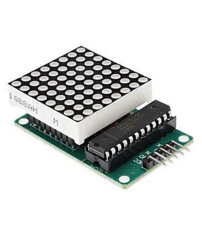
MAX7219 8X8 Red Dot led matrix module MCU control LED Display module for Arduino
SKU: 10007656
Reward Points: 10
Availability: In Stock
-
Fast delivery
-
Satisfaction guarantee
Key Features
The MAX7219 is an integrated serial input / output common-cathode display driver, it isconnected to a microprocessor with 8-digit 7-segment digital LED display can also be connectedto the bar graph display or 64 separate LED. On B BCD encoder including an on-chip, multi-channel scanning loop word drive, but also an 8 x 8 static RAM is used to store each data. Only one external register is used to set the current of each LED segment.
A convenient four-wire serial interface can connect all general-purpose microprocessor. Each data can be addressed in the update does not need to rewrite all the display. MAX7219 also allows the user to select on each data coding or non-coding.
The entire device contains a 150μA low-power shutdown mode, analog and digital brightnesscontrol, a scan-limit register allows the user to display the 1-8 bits of data, as well as a let allLED light detection mode.
Only need three IO ports can drive a dot-matrix! Dot-matrix display, flicker-free! Supports cascading
Module parameters:
A single module can drive an 8 * 8 common cathode lattice
2 module operating voltage: 5V
Module size: 5 cm in length X width 3.2 cm x 1.5 cm
4 with four screws hole, aperture 3mm, Our M3 Tongzhu fixed
5 modules with input and output interface, supports multiple modules cascade
Wiring instructions:
Module on the left as an input port, output port on the right.
Control of a single module, simply input port to the CPU
3 more modules cascade input termination module of a CPU, 2 output termination module inputand output of the two modules is terminated with the input end of the first three modules, and so on. ..
51 MCU, for example:
VCC → 5V
GND → GND
DIN → P22
CS → P21
CLK → P20


